We (the Healthcare Robotics Lab at Georgia Tech) have developed an additional module for an Invacare fully electric hospital bed (Model 5410IVC) so that the bed can be controlled from a web-based interface. This module can be easily plugged between the hand control and the Invacare bed, without having to modify any existing hardware on the bed. We call a bed so modified an ‘Autobed.’ With this feature, users who are unable to operate the standard bed controls, but can access a web browser, are able to position the bed by themselves without having to rely on a caregiver (for example, patients with quadriplegia). This page describes how to make the Autobed module using relatively inexpensive, commercially available hardware. Note: Documentation and build instructions for the older, deprecated Autobed v1 are available here.
WARNING: THIS WEB PAGE AND ITS ASSOCIATED CONTENTS DESCRIBE PROTOTYPE RESEARCH HARDWARE AND SOFTWARE. USING THESE MATERIALS OR DERIVATIVE MATERIALS COULD ENTAIL RISKS, INCLUDING THE RISK OF SERIOUS BODILY HARM. AS DETAILED IN THE SOFTWARE LICENSE AND HARDWARE LICENSE, WE PROVIDE THIS INFORMATION “AS IS”, WITHOUT WARRANTY OF ANY KIND, EXPRESS OR IMPLIED.
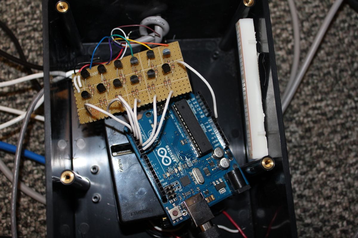
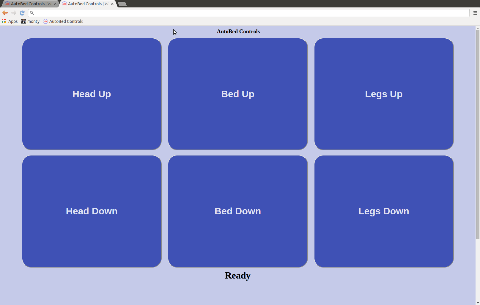
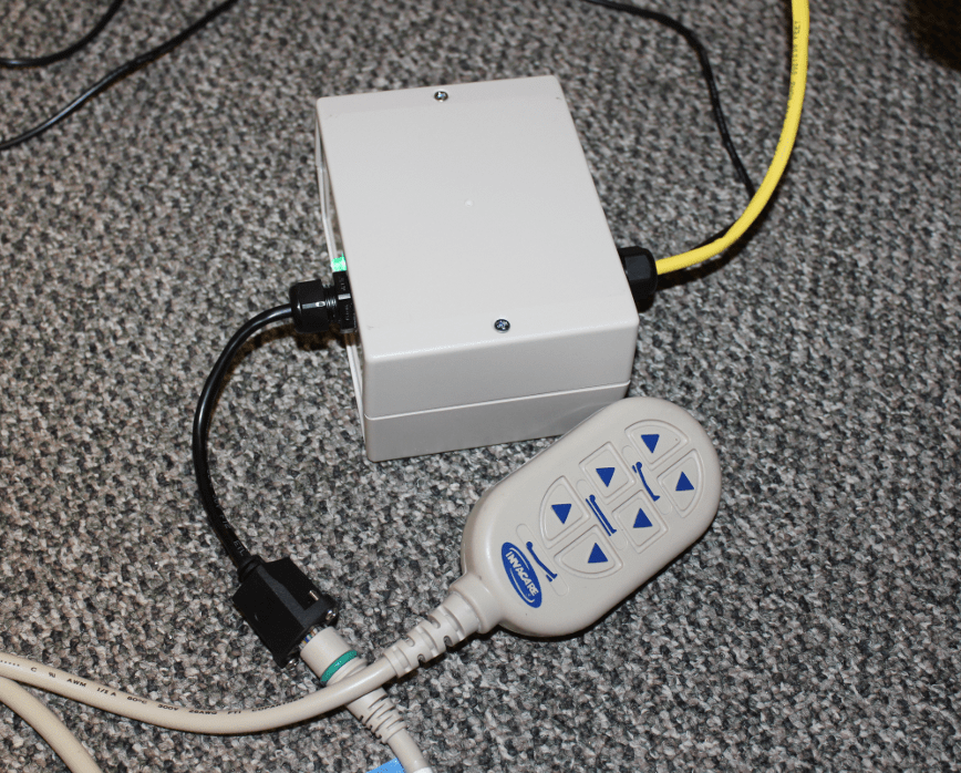
Once completed, the Autobed module plugs in between the hand control unit (provided with the bed by the manufacturer), and the bed controller box as shown in the image below (left image). A web interface (like the one in the image to the right) can be used to control the bed.
 |
 |
Warning: The bed may be damaged if the 2 right-most pins (pins #1 and #2 of 10) of the handset jack on the motor control box are electrically shorted while the bed is powered. For this reason, unplug the bed from power before making any modifications or before attempting to connect or disconnect the Autobed adapter box to the bed.
Table of Contents
- Overview
- Raw Materials and Equipment
- Open Hardware: Building the Autobed
- Open Source Software: A Web Controlled Autobed
- Using the Autobed
- Troubleshooting
- Additional Notes
- Support
- License
- The Team
Overview
Autobed Estimated Price: ~$80
Invacare Bed and Mattress Estimated Price: ~$2000 MSRP (out-of-pocket costs may be lower with Medicare subsidy in US, or if purchased from 3rd-party sellers)
Total Estimated Time: ~4:30 (hrs:mins)
The Autobed adapter box is arranged as follows: A Raspberry Pi single-board computer serves a web interface. When a web-browser loads the web interface, it makes a websocket connection to the Raspberry Pi. Commands from the web interface control the General-purpose input/output (GPIO) pins of the Raspberry Pi. The digital GPIO signals control an optoisolator circuit that mimics the hand-controller typically used with the bed. The original hand controller is connected in-line, and continues to work as usual, even when the Autobed adapter box is powered off.
The process of creating the Autobed adapter box occurs in three main stages: assembling the control circuit, assembling the connection and enclosure hardware, and installing the software. In the first section, ‘Open Hardware: Building the Autobed’, we describe how to construct the Autobed adapter box to relay commands from the web interface to the bed control box. In the second section, ‘Open Source Software: A Web-Controlled Autobed’, we describe how to setup the software for the Autobed adapter box on a Raspberry Pi. We provide detailed instructions for each step along with usable code. The pictures below show the finished Autobed system.

 |
 |
NOTE: We have developed and tested this method on the Invacare model 5410IVC bed, and it may or may not work for other models manufactured by Invacare. Do not attempt this modification on hospital beds from other manufacturers. By performing this modification, you will probably void the warranty on your bed, so proceed with caution.
Skills Required:
- Basic tool usage
- Through-hole Soldering
- Basic Familiarity with the Raspberry Pi
Raw Materials and Equipment
Here are the required materials and equipment with suggested retailers. You may be able to find these materials at lower prices from other vendors depending on your location. See the alternatives column of the tables below to see if an alternative part can be used.
- Invacare Bed
- Tools Required:
- Soldering iron, w/small diameter solder
- Phillips screwdriver
- Needle-nose pliers
- Wire stripper
- Multimeter
- Shear cutter (for clipping wire after soldering to PCB)
- Drill (Drill Press preferred), w/5mm and 3.5mm bits
- Hot Glue Gun, w/Hot Glue Stick
- Felt-tipped Pen/Marker
- Computer
- Parts Required:
| Raspberry Pi and Accessories | ||||||
|---|---|---|---|---|---|---|
| Description | Vendor | Part # | Quantity | Cost | Total | Alternative |
| Raspberry Pi Model B + 512MB | Element14 | – | 1 | $25 | $25 | Another model of the Raspberry Pi with 2×20 GPIO pins (Raspberry Pi 2, B+, A+) |
| 8+ GB Micro SD Card | Amazon | – | 1 | $8.95 | $8.95 | Compatible SD Cards |
| SD card reader/writer | – | – | 1 | – | – | May be built in on your computer |
| Wireless USB adapter or Ethernet cable | Amazon | – | 1 | $9.23 | $9.23 | Any RPi Compatible Wi-Fi Adapter |
| Circuit Components | ||||||
|---|---|---|---|---|---|---|
| Description | Vendor | Part # | Quantity | Cost | Total | Alternative |
| Perma-Proto HAT for Pi Mini Kit | Adafruit | 2310 | 1 | $4.95 | $4.95 | – |
| Brass M2.5 Standoffs for Pi HAT | Adafruit | 2336 | 1 | $0.75 | $0.75 | – |
| 22-24 AWG solid-core insulated wire | Sparkfun | 8022 | 1 | $2.50 | $2.50 | Any wire suitable for prototyping. |
| 1/8 watt 150 ohm resistor | DigiKey | CF18JT150RCT-ND | 6 | $0.10 | $0.60 | Any 150 ohm (+/-5% or less) resistors |
| PS2501-1-A optoisolator (1-channel) | Digikey | PS2501-1A-ND | 6 | $0.52 | $3.12 | Also available in 4-channel chips. Need 6 channels total. |
| 7-pin Male PCB Headers | Molex | 22-27-2071 | 2 | $0.49 | $0.98 | Various Suppliers |
| 7-circuit Molex Crimp Housing | Molex | 22-01-2075 | 2 | $0.45 | $0.90 | Various Suppliers |
| Crimp Terminals | Molex | 08-50-0136 | 14 | $0.72 | $1.01 | Various Suppliers, Spares recommended |
| Breakaway Headers | Sparkfun | PRT-00116 | 1 | $1.50 | $1.50 | Various Suppliers |
| 2-wire Jumpers | Sparkfun | PRT-10362 | 1 | $0.95 | $0.95 | Various Suppliers |
| Green LED | Sparkfun | COM-09592 | 1 | $0.35 | $0.35 | Various Suppliers |
| Enclosure and Mounting Hardware | ||||||
|---|---|---|---|---|---|---|
| Description | Vendor | Part # | Quantity | Cost | Total | Alternative |
| Plastic Box (Autobed Housing) | Digikey | HM1095-ND | 1 | $7.51 | $7.51 | Any box in which holes can be made easily that is at least 5″x 4″x 3″ |
| Raspberry Pi Plastic Case | Adafruit | 2285 | 1 | $5.00 | $5.00 | NO LID REQUIRED |
| Strain Relief Cord Grip | McMaster-Carr | 69915K52 | 1 | $2.82 | $2.82 | Any strain relief grip for ~0.19mm cable |
| Female to Male Ethernet Cable | Cable Leader | C5203-3200 | 1 | $3.17 | $3.17 | Any female to male Ethernet extension cable |
| 2+ ft. Ethernet cable | Newegg | N82E16812452074 | 1 | $0.99 | $0.99 | Any Ethernet cable |
Open Hardware: Building the Autobed
This section describes the assembly of the hardware necessary to relay inputs from the web interface to the bed.
Total Estimated Time: ~2:30 (hrs:mins)
Electrical Circuit Assembly
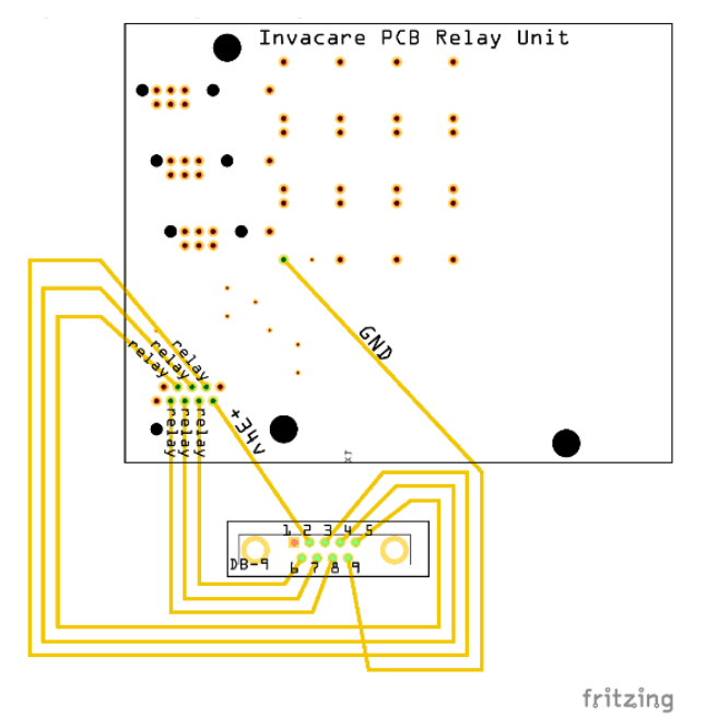
The Invacare Bed is designed to be operated by a six-button, corded remote control. This control plugs into the motor control box (MCB) with a 10-wire, Ethernet-like cable. When connected to the MCB, pin #2 on this cable carries 35V to the handset. Each button in the handset is a physical switch, which, when closed, allows 40 mA of current to flow from the 35V line back into the MCB where it activates one of 6 relays (1 per motor direction). This relay then engages one of the motors, moving the bed.
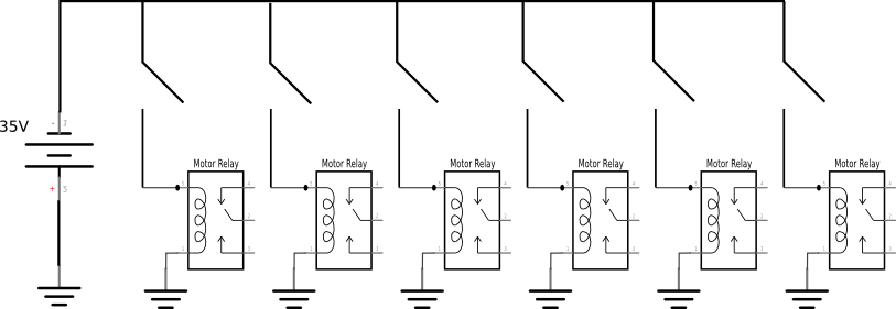
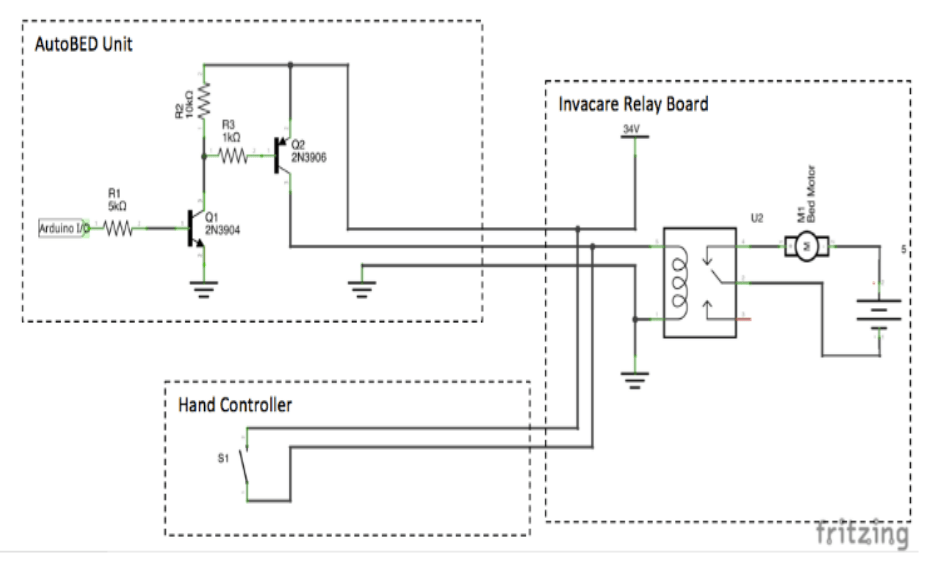
A circuit can be constructed that uses optoisolators to emulate these physical buttons on the hand remote. A optoisolator (also called an ‘optocoupler,’ or ‘optoisolator’) contains a light-emitting diode (LED) and a light-sensitive transistor. When current (here, from a GPIO pin on a Raspberry PI) flows through the LED, the light produced allows current to flow through the light-sensitive transistor. We use six of these optoisolators to allow current to flow from the 35V wire back to each of the motor relays. The schematic below shows the circuit diagram for micro-controller command of a single relay. This circuit will be repeated 6 times, once for each relay.

A Perma-Proto Mini HAT from Adafruit provides the base for the circuit used to control the Autobed system from the Raspberry Pi. This prototyping board connects securely to the Raspberry Pi, exposes the needed GPIO pins, and provides sufficient room for the required circuit components in a compact size. Instructions for building the circuit follow with detailed pictures.
Parts Needed:
- Soldering Iron w/Solder
- Multimeter (to check circuit)
- Solid-core wire
- 1 Perma-Proto Mini HAT
- 6 PS2501-1-A optoisolators
- 7 150 ohm resistors
- 2 7-pin male, polarized PCB headers
- 1 2-pin breakaway header
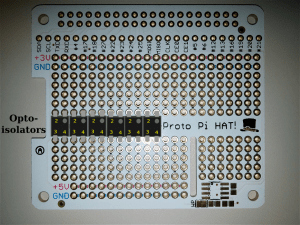
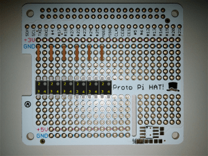
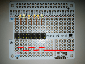
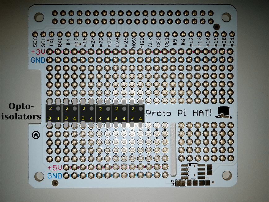
NOTE: All subsequent instructions will refer to the board as viewed from above (looking at the labeled, printed side) with the header at the top (as seen in the following images).
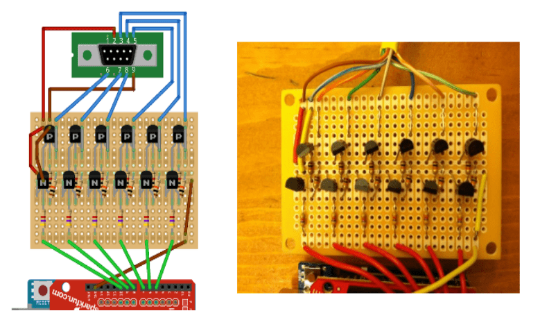
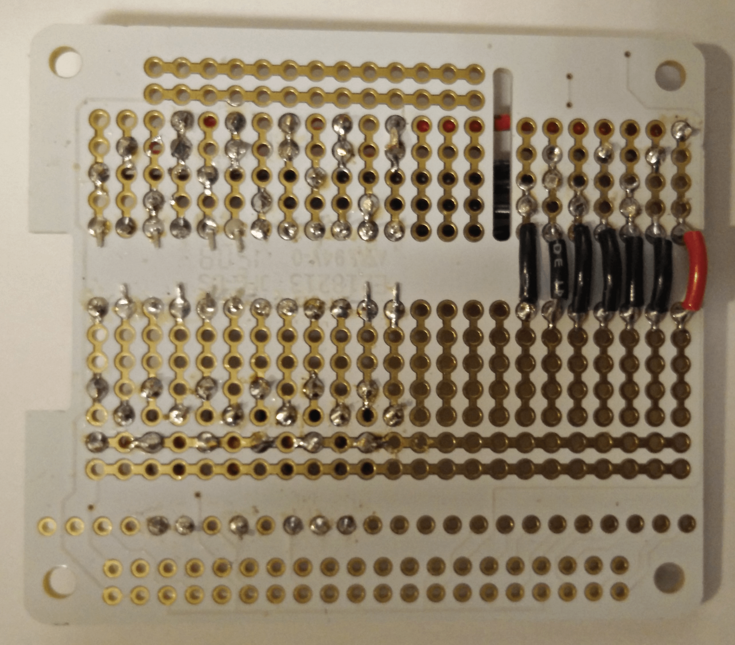
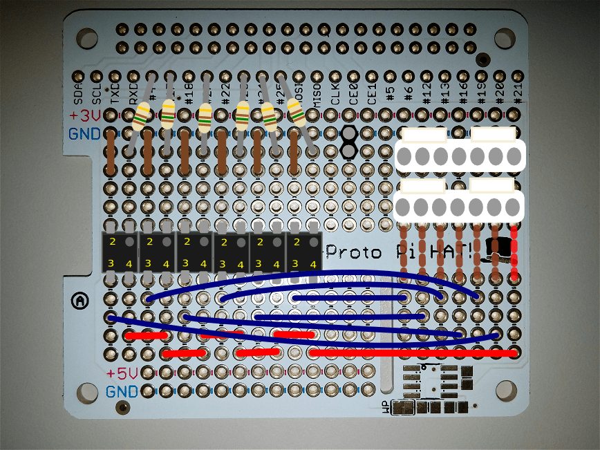
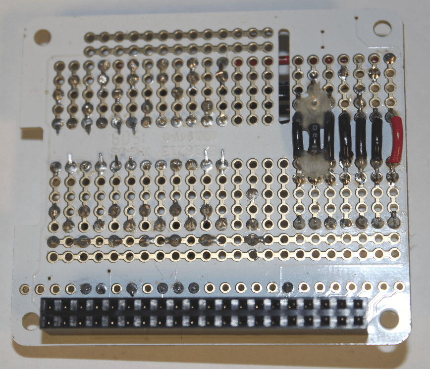
- (Estimated time: 15 mins) We first place the optoisolator chips onto the Perma-Proto board. Solder each of the optoisolator chips into place, across the central span, end-to-end in consecutive columns of the Perma-Proto board, with pins 1 and 2 on top side (nearest the GPIO breakouts and GPIO Header (there is a dot on the chip by pin 1, and a groove along the edge of the chip on the same side as pins 1 and 2)). Start at the left edge the Perma-Proto board. The optoisolators should all be placed to the left of the groove cut for the Raspberry Pi camera cable.
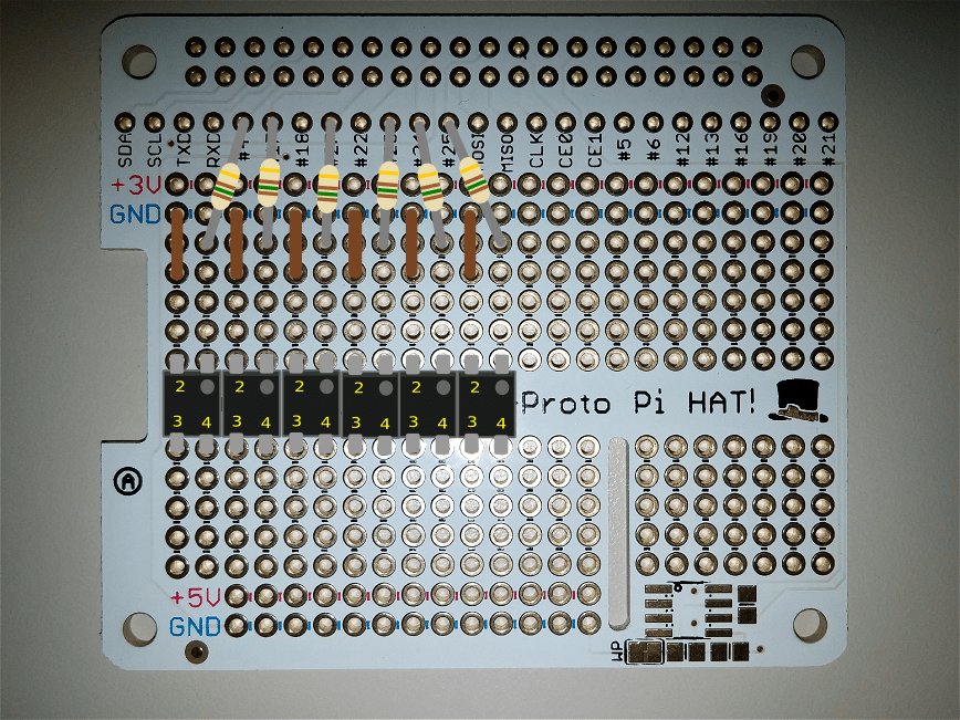
- (Estimated time: 20 mins) We then connect the cathode of the LED of each optoisolator (pin #2) to the Raspberry PI’s ground on the Perma-Proto board. Solder wires from the Perma-Proto board’s ground strip near the top of the board to any hole in the column of pin #2 on each optoisolator chip. Pre-cut and stripped jumper wires may be useful here, but are not necessary.
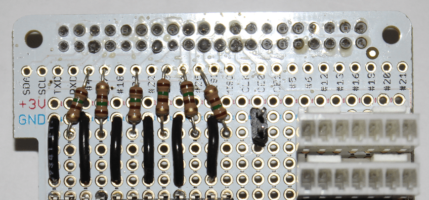
- (Estimated time: 10 mins) We next connect software-controllable GPIO outputs from the Raspberry PI to the anode of the LED of each optoisolator through a 150 Ohm current-limiting resistor. The 150 Ohm resistance is chosen to maximize the current through the optoisolator LED without drawing more power than is allowed from a single GPIO pin on the Raspberry PI. Solder a 150 Ohm resistor to pin 1 of each optoisolator chip from GPIO through-holes 4, 17, 27, 23, 24, and 25 respectively from left to right. Ground wires and 150 Ohm resistors will now alternate down one side of the optoisolators, in 6 pairs. This completes the inputs to the optoisolators.
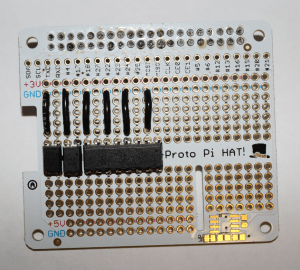
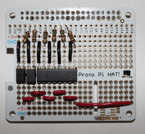
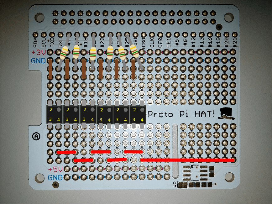
- (Estimated time: 20 mins) We next need to connect the 35V source from the motor control box to the collector of the output transistor of each optoisolator (pin #4). Solder a wire from the the bottom right corner through-hole on the Perma-Proto board (will be connected to the 35V line later) to the bottom hole in the row connected to pin 4 of the right-most optoisolator.Now, solder a wire from the second-to-bottom hole in the same row to the second-to-bottom row connected to pin 4 of the next optoisolator (two columns to the left). Now connect the bottom hole of this row with the bottom hole connected to pin 4 of the 3rd optoisolator. Continue this alternating pattern until the optoisolators have all been connected together via pin 4 (see images below). Pre-cut and stripped jumpers may be useful here, but are not necessary.
- (Estimated time: 20 mins) We next need to connect the 35V source from the motor control box to the collector of the output transistor of each optoisolator (pin #4). Solder a wire from the the bottom right corner through-hole on the Perma-Proto board (will be connected to the 35V line later) to the bottom hole in the row connected to pin 4 of the right-most optoisolator.Now, solder a wire from the second-to-bottom hole in the same row to the second-to-bottom row connected to pin 4 of the next optoisolator (two columns to the left). Now connect the bottom hole of this row with the bottom hole connected to pin 4 of the 3rd optoisolator. Continue this alternating pattern until the optoisolators have all been connected together via pin 4 (see images below). Pre-cut and stripped jumpers may be useful here, but are not necessary.


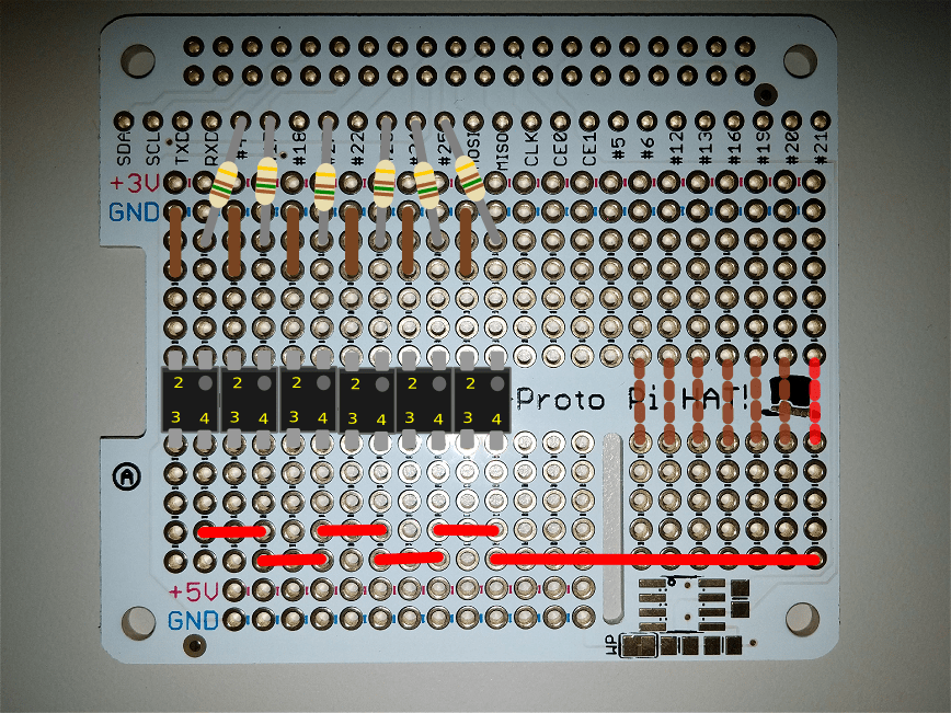
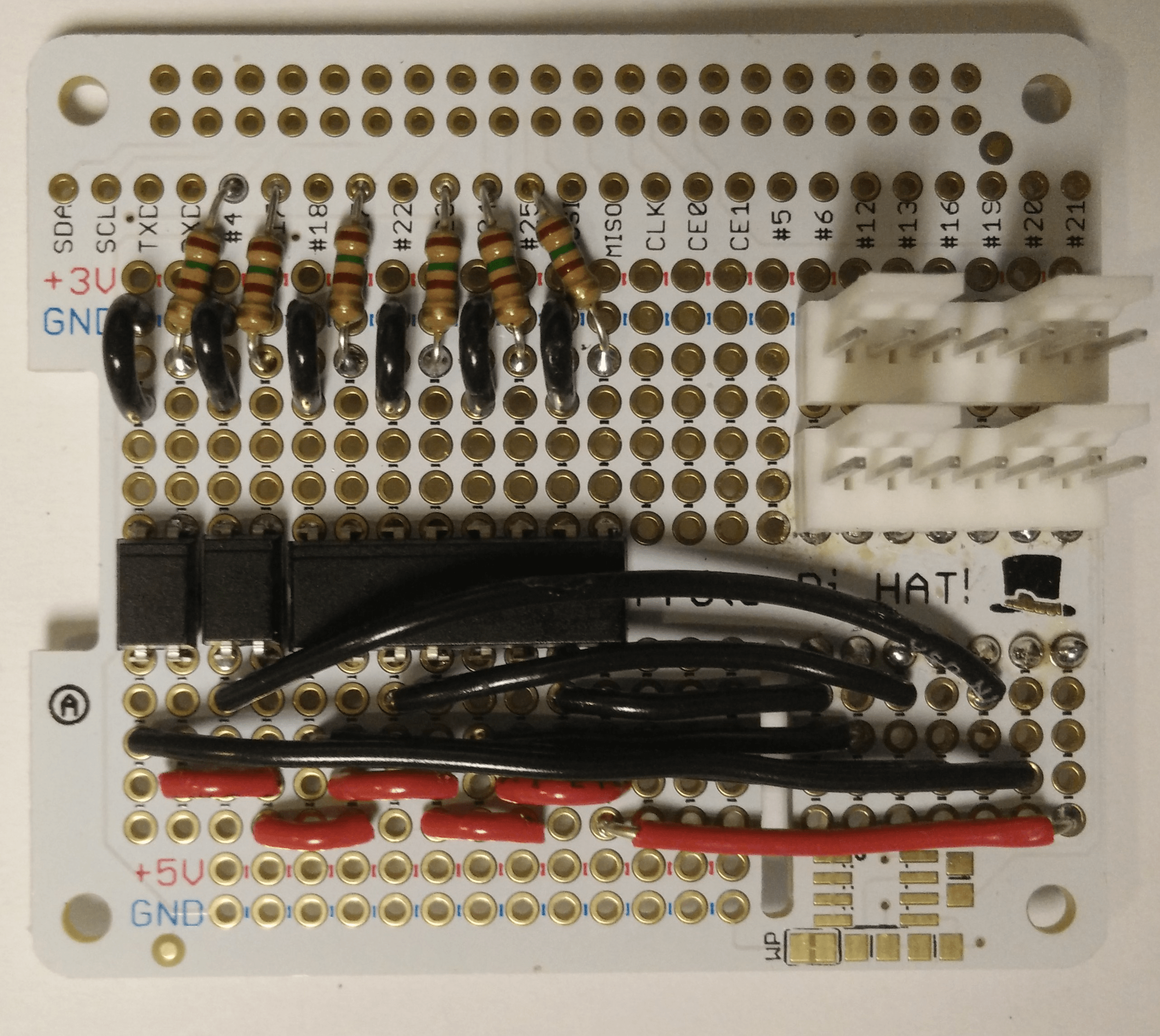
- (Estimated time: 20 mins) We next connect the emitter of the transistor in each optoisolator to its own output channel (directing the current back to the appropriate relay in the motor controller box). Using the two rows remaining, solder wires from pin 3 of each optoisolator to one of the 6 remaining rows at the right of the Perma-Proto board, between the camera-connector slot and the right edge of the board.To avoid changing software later, make sure to connect the emitters in the following manner: Connect the closest two points first: pin 3 of the right-most optoisolator to the first column to the right of the camera connector slot (left-most of the 7 columns with vertical jumpers). Connect pin 3 of the next optoisolator to the next column to the right, and so on, working outward in both directions. See the image below for reference. It is probably best to lay out these connections before soldering to determine the best layout, as wires will need to overlap.
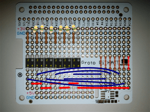
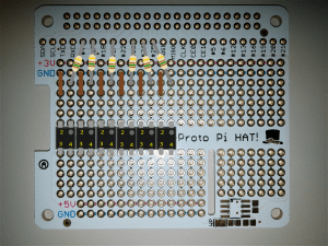
- (Estimated time: 15 mins) Finally, we will add two polarized PCB headers to the Perma-Proto board so that connections coming in from the hand-held control pad and out to the motor control box can be made securely and correctly. Solder the first male PCB header to the top of the Perma-Proto board across the right-most pins, with the locking mechanism toward the top of the board. Then, solder the second male PCB header across the same seven pins in the second-to-bottom row above the central gap, leaving space between then so that they are accessible.
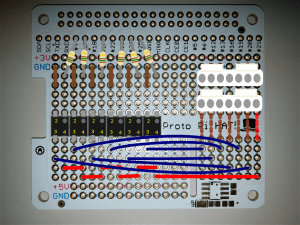
- (Estimated time: 3 mins) To have some feedback about when the Autobed adapter box is plugged in and running properly, we will add a single LED, controlled by one of the GPIO pins, to indicate when the software is running and receiving input from the web interface. We recommend a green LED, as red, yellow, and orange typically indicate errors, but any color may be used. To add the LED, solder a 2-pin header to the Perma-Proto board with one pin in the ground rail and the other pin in the top hole of one of the free columns, between the inputs to the optoisolators and the PCB headers.

- (Estimated time: 2 mins) Next, solder another 150 Ohm resistor from the number 5 GPIO through-hole to the column with the breakaway header from the previous step. A 2-wire jumper will connect the header pins to the LED mounted in the side of the enclosure.

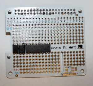
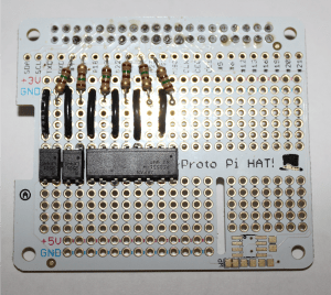
- (Estimated time: 10 mins) Finally, solder the provided GPIO header onto the Perma-Proto HAT (2×20 holes along edge of HAT board).

- (Estimated time: 10 mins) Lastly, we should check that the circuit has no accidental shorts or defects. Using the multimeter (in continuity mode, click here for more info), check each of the connections, and ensure that: All of the optoisolator #4 pins are connected to each other, and the far-right row of the board, but not to any other locations or optoisolator pins. Confirm that all pins 3 of the optoisolators are connected to the header pins, 1 each, in order, and not to one another or the 35V line (connected to pins 4). Confirm that pin 2 of each optoisolator is connected to the ground rail and not to any of the number 1 pins. Also confirm that each optoisolator pin 1 is connected with a resistance of ~150 Ohms to the intended GPIO breakout location. Once the circuit is correct, proceed to next section in which the housing will be constructed.


Enclosure, Electrical Connections, and Assembly
The Autobed adapter box hardware is housed in a plastic enclosure which can be mounted to the Invacare Bed. This enclosure contains the Raspberry Pi and Perma-Proto HAT assembled above. The enclosure must be modified to allow cables for connecting the Autobed adapter box to the Bed’s motor control box to pass through as well as cables connecting the hand-held controller to the Autobed adapter box which will allow the hand controller to continue to operate as normal. Modifications must also be made so that the power cord for the Raspberry Pi can pass through as well. An LED is mounted through the side of the box to indicate when the Autobed adapter box is powered and running properly.
In this section, we will run two Ethernet cables into the enclosure, one with a female socket outside the enclosure for connecting the Invacare handset, and the second with a male plug outside the enclosure to plug into the motor control box on the Invacare bed. These cables should pass through opposite sides of the enclosure via strain-relief bushings to prevent any force on the cables from pulling the electronics inside the enclosure. We will also make a slot for the micro-USB power cord for the Raspberry Pi to enter the enclosure, and mount the activity LED and connect it to the circuit board.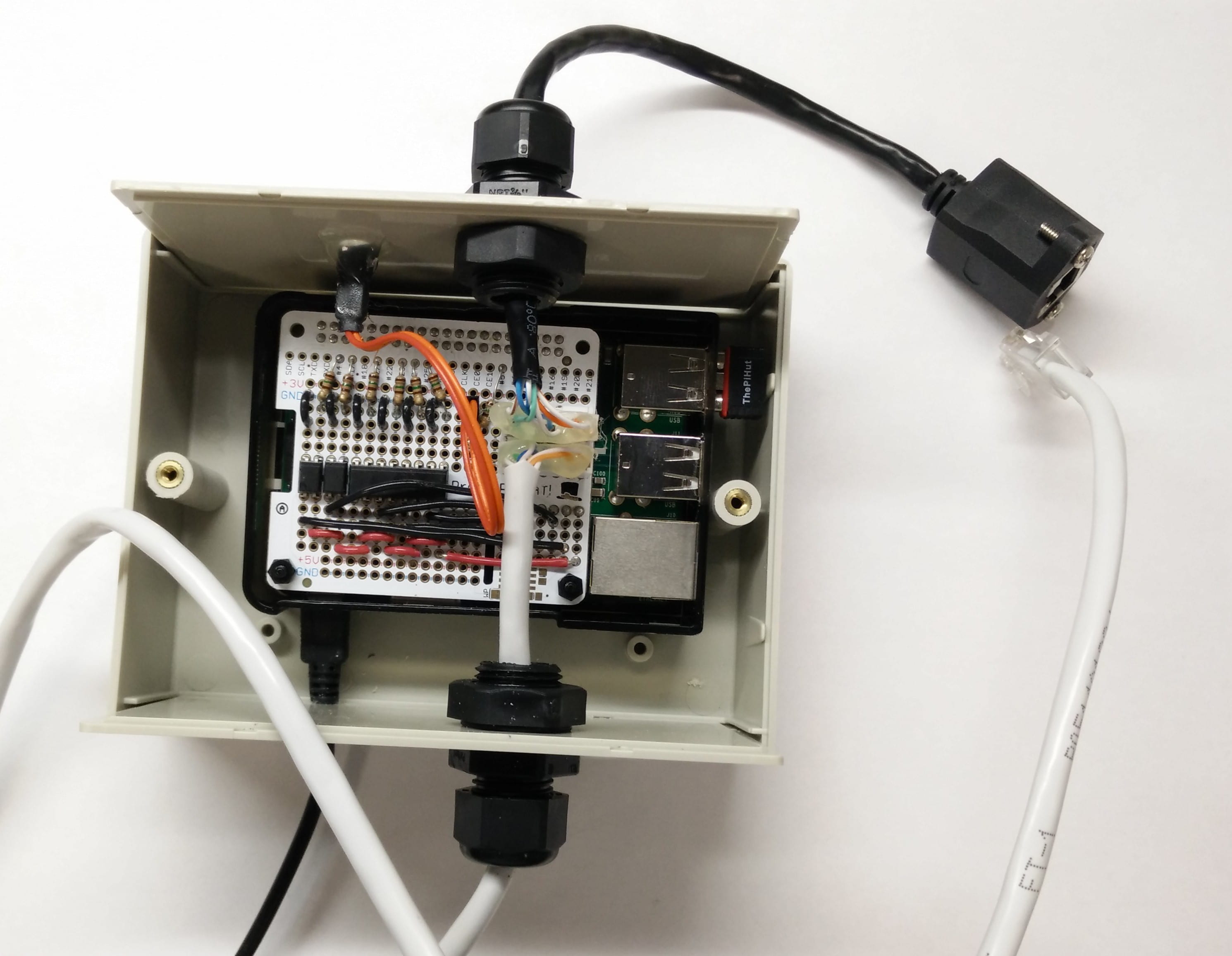
Parts Needed:
- Soldering Iron w/Solder
- Multimeter
- Drill w/5mm and 3.5mm bits
- Small-diameter file
- Hot Glue Gun w/Glue Stick
- Felt-tip pen/marker
- Terminal Crimping Tool
- 1 Plastic enclosure at least 3″x4″x5″
- 1 Raspberry Pi Case
- 1 M/F Ethernet extension
- 1 2′ length of Ethernet cable
- 2 7-circuit crimp housings
- 14 crimp terminals
- 2 strain relief cord grips
- 1 green LED
- 1 4″ 2-wire jumper
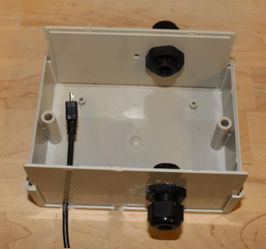
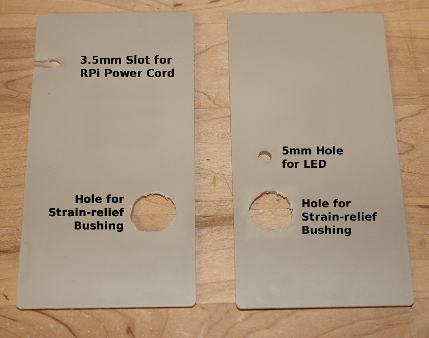
- (Estimated time: 15 mins) The cables will terminate inside the box to the 7-pin Molex connectors, which will attach to the male PCB headers on the circuit already built. The holes for the strain-relief bushings should be placed so that the cables can travel easily from the inside of the bushing to the PCB headers on the circuit. For simplicity, all holes will be made in the two removable side panels of the enclosure. A good location for the strain-relief bushings seems to be toward the top of the panel, slightly more than 1/2 way across the longer direction (see image). It is helpful to place the Raspberry Pi in its case, attach the Perma-Proto HAT to the Raspberry Pi (including standoffs), and place it in the enclosure to estimate a preferred location. It is preferred to place the end of the Raspberry Pi AWAY from the USB and Ethernet ports against one wall, to leave as much room as possible for these ports on the opposite side. The strain relief bushings should line up with the PCB headers, so that the incoming cables are required to bend as little as possible.
 Once the desired location for the holes has been identified, trace the bushing to mark the desired location on the inside of each panel. Then, using the 5mm drill bit (or larger, if available), drill away as much of the material within the desired hole as possible, and use the file to shape and extend the hole as necessary to fit the strain-relief bushing, checking the hole against the bushing regularly to avoid removing too much material. The plastic of the case files easily by hand with a medium-roughness file. Repeat this procedure for both bushings, one in each panel.
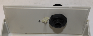
 - (Estimated time: 10 mins) We also need to add a hole to one side panel to allow the LED to be mounted. To place the LED, drill a 5mm hole, in line with the strain-relief bushing in the wall panel which will be nearest the PCB headers on the Perma-Proto HAT (and nearest to the LED pins). The hole should be beside the hole for the strain relief bushing, allowing some separation. A diffused LED is preferred, so that it is easier to see whether the LED is active from all directions. If the LED is clear (not diffused), sandpaper can be used to score the surface of the plastic dome, which will effectively diffuse the light. Place the 5mm Green LED into this hole so that the wire leads are on the inside of the panel, and the plastic dome is outside. Secure the LED into place using a small amount of hot glue on the inside of the panel. Once secured, use a marker to note the Anode (+) and Cathode (-/GND) of the LED (the longer lead is the anode), and trim the leads down to approximately 3/8″, so that they will fit into the slots of the 2-wire F/F jumper. As the leads are narrow, the jumper may be secured to the LED using hot glue.
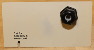
- (Estimated time: 10 mins) Lastly, we need to make a passage for the power cable of the Raspberry Pi. We will cut a narrow groove into the side of the panel without the LED to allow the cable in. To estimate the best location, place the Raspberry Pi (in its case) into the enclosure with the sides in place, so that the LED side-panel is AWAY from the Raspberry Pi’s micro USB port. Mark the bottom of the panel where it aligns with the Raspberry Pi’s micro USB port.Using the 3.5mm drill bit, drill a hole just above the groove in the edge of the side panel where it fits into the base, and further holes to the near edge to make a clear channel for the cable to be set into. Use a small hand file to smooth out these edges and make the groove at least 3.5mm wide along the full width. Check progress by gently attempting to slide the power cable into the groove.
- (Estimated time: 5 mins) Once these holes are all cut and properly sized, attach the strain-relief bushings to the panels, so that the adjustable cord-grip is facing outward.
- (Estimated time: 5 mins) Once the strain-relief bushings are in place, cut the male Ethernet plug off of the M/F Ethernet adapter cable, and feed the cable into the bushing so that the female jack is to the outside of the box. Feed the cable completely through to leave as much loose cable as possible while attaching the connector to the recently cut end. Repeat this procedure with the 2+ ft. Ethernet cable, leaving a male Ethernet plug outside of the enclosure.
- (Estimated time: 10 mins) We will now attach each of the Ethernet cables to a female connector housing, which will connect to the PCB headers. Start by removing one inch of the cable shroud from the cut end of each Ethernet cable, exposing the 8 wires (typically in 4 twisted pairs, separate and fan out as necessary). Next, strip slightly over 1/8 inch of the insulation from each of the wires.
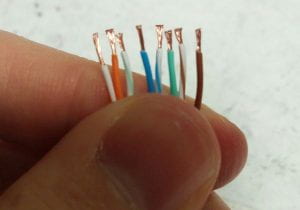
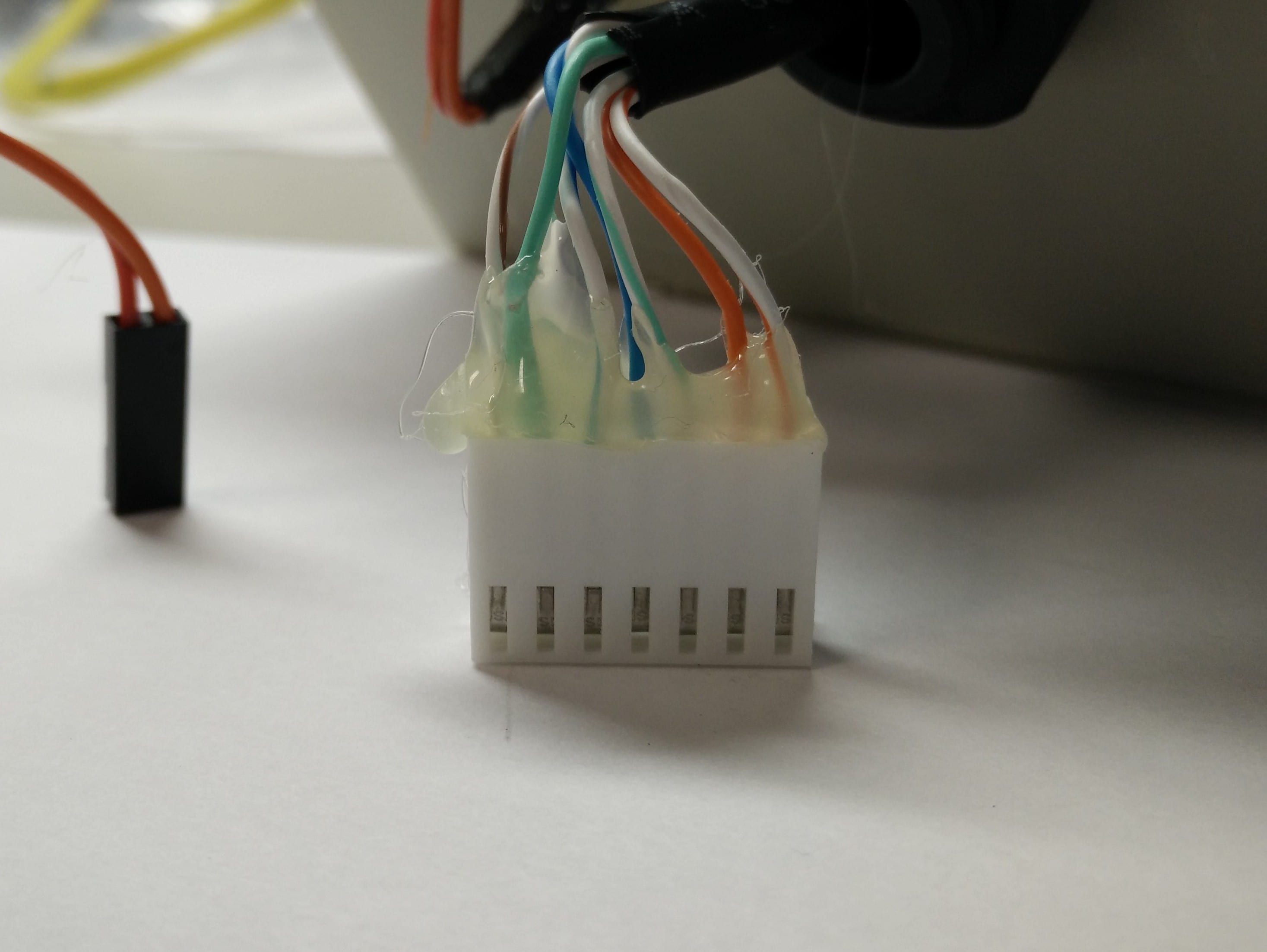
- (Estimated time: 30 mins) To make a secure electrical connection with the male pins of the PCB headers, we will attach crimp terminals to the wires of the Ethernet cables. These terminals are then inserted into the female housing, forming half of the connector. The crimp terminals and housing provide a mechanically secure, electrically sound connection, and the polarized connector prevents the pieces from being connected improperly. However, the crimp terminals can be delicate. If properly crimped, they should fit easily into the housing and stay secured by a locking tab. However, improper crimping, bending, or other problems can make this difficult. For this reason, a crimping tool is recommended, though this can be done carefully with needle-nose pliers. Also, if the terminals are connected by a metal strip, be sure to cut away the ‘wings’ from the connectors completely. It is recommended to read or review this page from Molex and this thorough tutorial before beginning the crimping process. Practicing on spare wire with extra terminals may also be useful. Begin by fanning out the wires in the Ethernet cable in the order they are in within a traditional connector: orange-white, orange, green-white, blue, blue-white, green, brown-white, and brown (more information and image available here). At this point, cut the solid brown wire short, at the base of the cable shroud, as it is not needed or used. Next, with the cables held in this order, left-to-right, begin attaching the crimp terminals to each wire, so that the springy loop faces away from you (orienting the terminals this way is not strictly necessary, but helps to avoid having to twist wires to fit all of the cables into the housing later.) Repeat this procedure for both cut Ethernet cables.
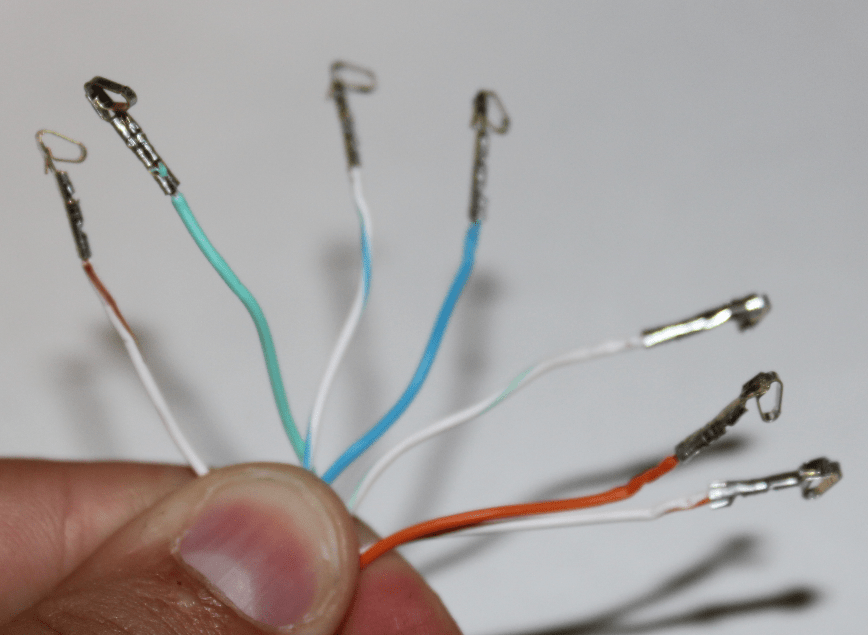
- (Estimated time: 10 mins) To further secure the connection between wires and crimp terminals both electrically and mechanically, a small amount of solder can be added to the wire to secure it to the terminal. Add a small amount of solder to the terminal near the exposed wire, being careful not to allow solder to contact the spring loop.
- (Estimated time: 5 mins) Finally, the terminals need to be inserted into the female connector housings. For each of the two cables: align the wires in the standard order (OW,O,GW,Bl,BlW,G,BrW,[Br]) from left to right. With the tabs on the connector housing (which are at the bottom of the housing) facing down, insert the crimp terminals from left to right in the above order. THE ORANGE-WHITE CABLE SHOULD BE ON THE END CONNECTOR WHICH CONNECTS TO THE FAR RIGHT PIN ON THE PERMA-PROTO BOARD. The orange-white wire carries the 35V input from the motor control box, and must connect to the line on the Perma-Proto board which powers all pin #4’s of the optoisolator outputs.
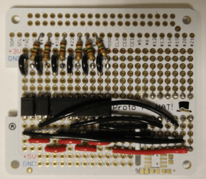
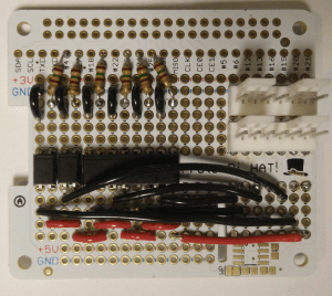
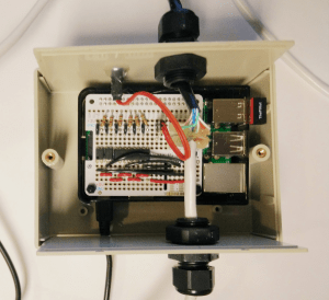
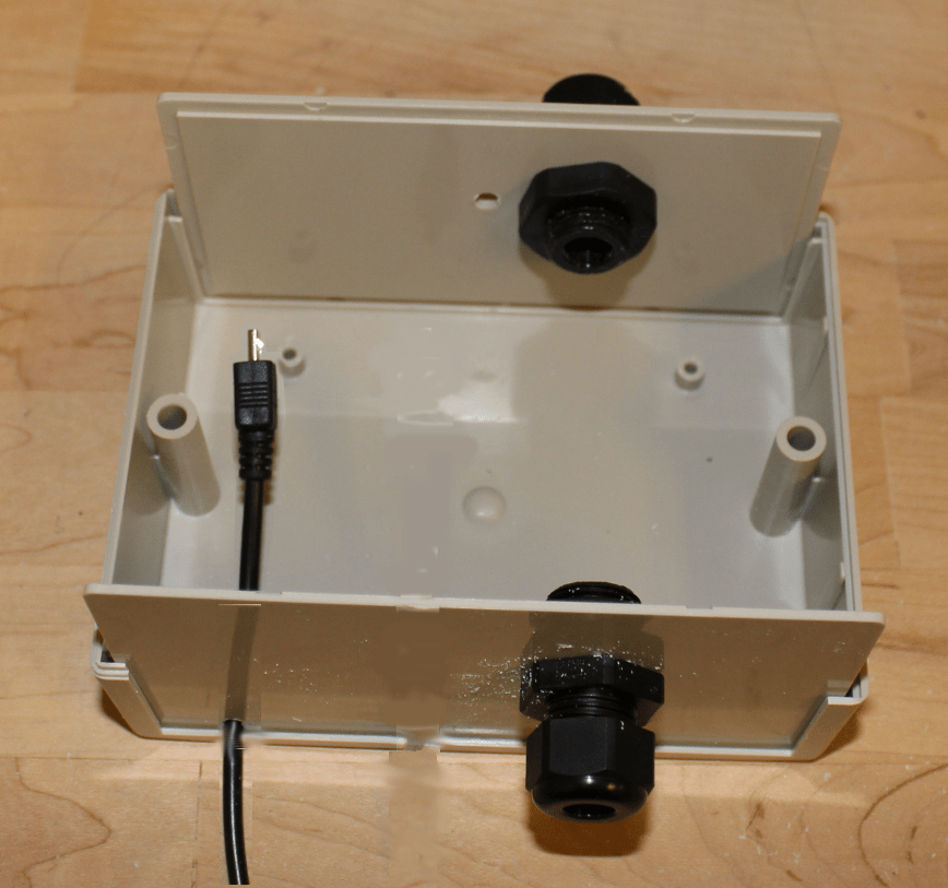
 This is what the enclosure looks like, after the all the necessary IO connectors are added to the enclosure.
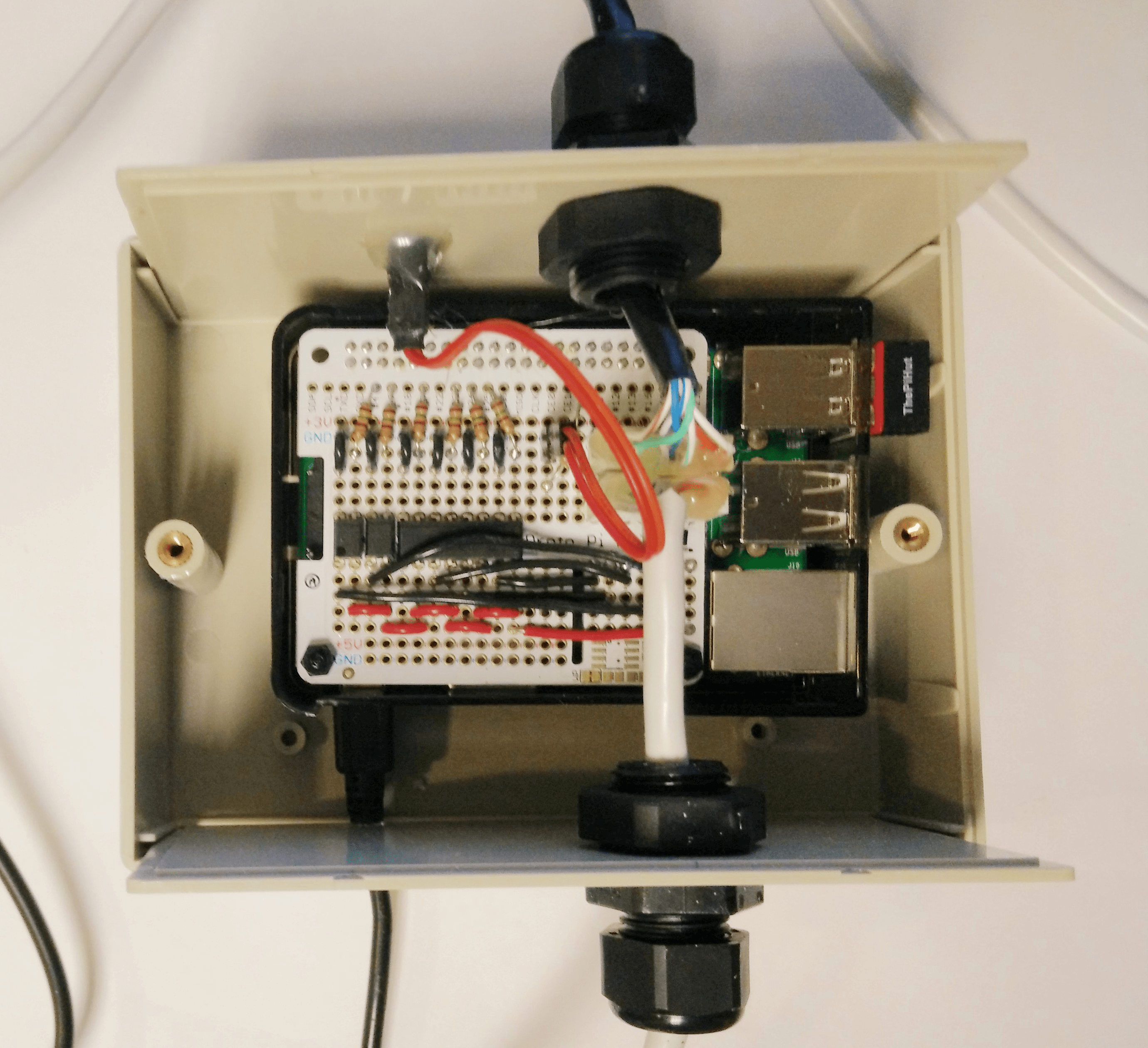
- (Estimated time: 10 mins) Once we have completed the connectors, the wires can be secured to the connectors using a small amount of hot glue across the top of the connector housing, especially if some of the locking pins do not appear to hold securely. The connectors can then be attached to the PCB headers (either connector can attach to either header, interchangeably). The side panels of the enclosure can then be moved back into place, feeding most of the excess cable to the outside of the box, so that the connectors are not strained by the cables. Once the cables are so arranged, secure them into place by tightening the outer cap of the strain relief bushing. At this point, the LED can also be connected to the Perma-Proto board using the 2-wire, 4″ F/F jumper. Connect the jumper so that the anode of the LED is connected to the GPIO via the 150 Ohm resistor, and the cathode is connected to the ground pin.
 (Estimated time: 5 mins) At this point, the hardware and enclosure assembly is complete. The following checks can be used to verify that the circuit is correctly connected. Using a multimeter in connectivity mode, verify that every pin #4 on the output side of the optoisolator is connected to the left-most pin in the female Ethernet connector (when the tab-slot is down). Similarly, verify that each of the pins #3 of the optoisolators are connected to one and only one pin in the female Ethernet connector. Finally, insert the male Ethernet connector into the hand-controller position in the Invacare motor control box (the tab can be left in place, and will hold the cable securely). To remove this cable later, first UNPLUG THE BED FROM POWER. The plastic retaining tab must be lifted using a plastic-coated paperclip or similar item to pry up the tab while pulling gently on the cable. Warning: The bed may be damaged if the 2 right-most pins (pins #1 and #2 of 10) of the handset jack on the motor control box are electrically shorted while the bed is powered. For this reason, unplug the bed from power before inserting any items to help remove this cable, and only use non-conductive items. Insert the hand-controller into the female Ethernet jack (this connection can be taped to ensure they do not come apart, since the tab has been removed from the handset’s connector). Plug in the bed, and the hand controller should work as normal (without any requirement for the Autobed adapter box or Raspberry Pi to be powered).


Open Source Software: A Web Controlled Autobed
Our open source software runs on the Raspberry Pi single-board computer. The Raspberry Pi serves as a web interface with buttons for each of the bed controls, and uses websockets to provide real-time interaction between the interface and bed movements. Full instructions on setting up the Raspberry Pi and installing the software are included below for two methods: Direct install of a pre-configured Raspbian Image, and manual installation.
Setting up the Raspberry Pi
There are two main ways to set up the autobed software on a Raspberry PI:
- Pre-installed Raspbian Image
- Install Script
If you only intend to use the Raspberry Pi as an Autobed controller, it is easiest to use the pre-installed Raspbian Image. This is a copy of Raspbian (2015-05-05-Raspbian-wheezy), with the Autobed software already installed and configured. Note: To keep the image size small, compontents of Raspbian required to run the graphical user interface (GUI) were removed; however, the command line interface is still accessible by connecting the Raspberry Pi to a monitor or by connecting via SSH over a wired network.
If you already have a Raspberry Pi with Raspbian installed, and want to test the Autobed software on your existing installation, an install script is available, which will completely install and configure the Autobed software for you, but which may interfere with existing setups (most notably an existing Apache configuration). For more fine-grained control of the install, the install script is commented, and the individual steps can be followed manually.
After either installation method, the Wi-Fi connection must be set up on the Raspberry Pi so that the web-based interface can be accessed.
Installing the Pre-configured Raspbian OS
- Download our zipped, pre-configured image of the Raspbian OS here.
- Unzip the image file once downloaded.
- Use the instructions located here to write the image file to an SD card. More information available here or here.
- Place the micro SD card into the slot on the back of your Raspberry Pi and plug it in to power (see the Raspberry Pi documentation for help with this step). The red power light on the Raspberry Pi should come on and the green activity lights beside it should start to flash as the Raspberry Pi boots. If the green activity light does not flash, you have not written the image file to the SD card correctly.
- Once booted, the Autobed’s hostname is ‘autobed-pi’, with username: ‘pi’ and password: ‘autobed’. We recommend running
raspi-cofigon the Raspberry Pi after booting. - In
raspi-config, you should select to:- Expand the filesystem (to use the full SD card size)
- Change the default password (and the username and hostname if desired)
- Enable graphical boot (if desired for further configuration)
- Change internationalization options: location and language (if desired)
Installing from Install Script
- Connect to a terminal on your Raspberry Pi (either via SSH, or else by opening a terminal in the graphical interface).
- Download the install script, make it executable, and run it:
wget https://github.com/gt-ros-pkg/hrl_autobed_dev/blob/2.1/web_only/install_autobed
chmod +x install_autobed
./install_autobed - (Advanced Users) The install script is a commented bash script, and each piece of the installation can be performed manually and modified as necessary to avoid conflicts with other installed software (notably existing Apache configurations).
Setting up Wi-Fi
- Plug the wireless USB adapter into one of the USB ports of the Raspberry Pi, and power the Raspberry Pi on.
- Once your Raspberry Pi has booted, access a terminal either via SSH by connecting to a wired network, or by opening a terminal in the graphical interface with a monitor and keyboard plugged into the HDMI/VGA and USB ports.
- Use these instructions to connect the Raspberry Pi to your wireless network.
- It is likely useful to assign a static IP address to your Raspberry Pi, to simplify opening the web interface. This can be accomplished following the directions here.
Using the Autobed
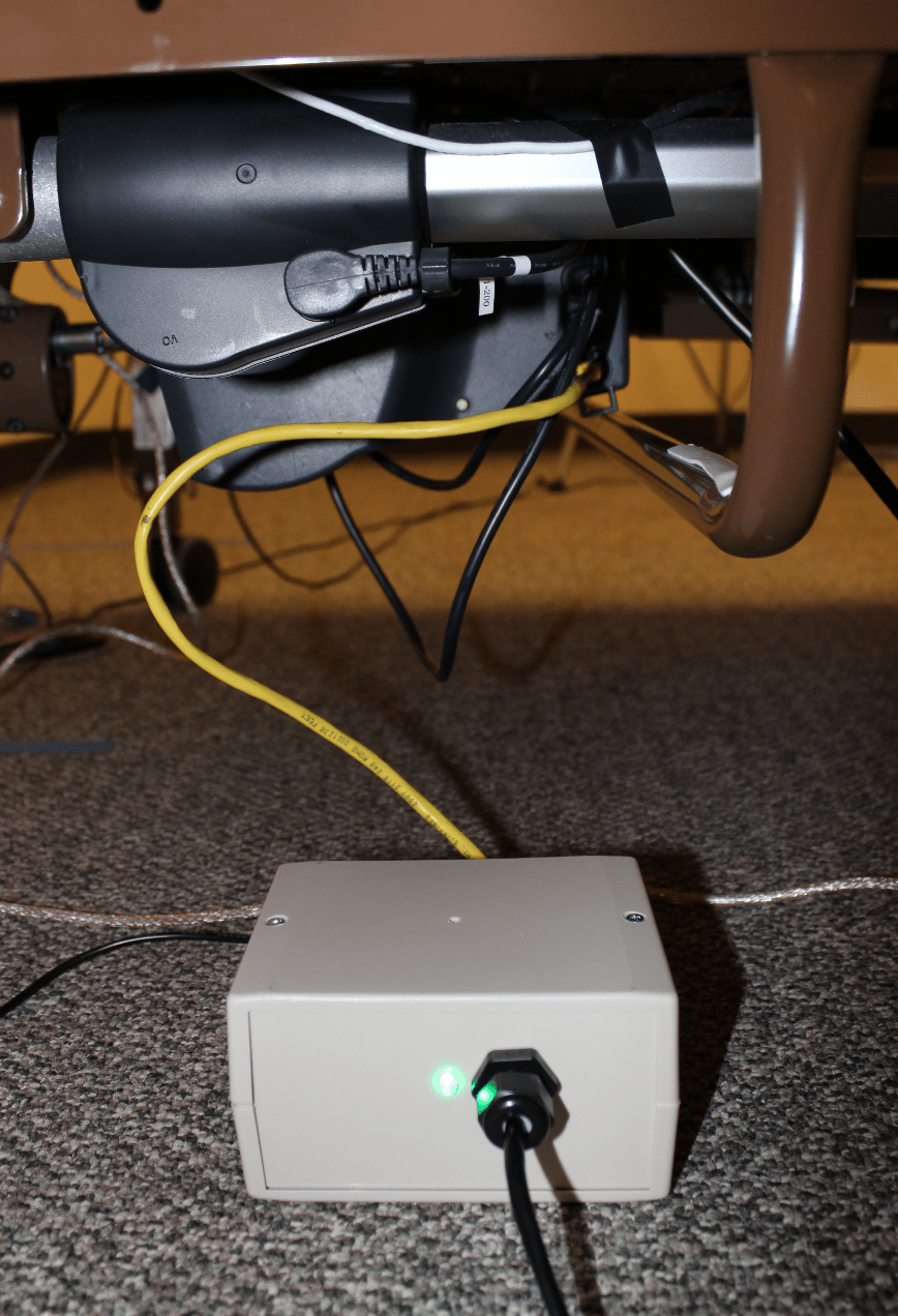
Once the Raspberry Pi boots properly, and the interface can be loaded on a browser on the local network, shutdown the Raspberry Pi and assemble the full setup within the enclosure.
Once the Autobed adapter box is fully assembled, unplug the Invacare Bed from power, and remove the hand-held controller from it’s plug in the motor control box.
Plug the male connector from the Autobed adapter box enclosure into the connector jack on the motor control box normally used for the hand controller, and connect the hand controller into the female Ethernet jack on the Autobed adapter box.
Leaving the Autobed adapter box unplugged from power, plug the Invacare bed back into power, and confirm that the hand controller still works as normal when plugged into the Autobed adapter box. This hand controller should function even when the Raspberry Pi on the Autobed adapter box is not powered.
Plug the Autobed Raspberry Pi into power. Once powered, the green LED on the Autobed adapter box will likely be dimly lit. After ~30-60 seconds, once the Raspberry Pi has finished booting, the green LED should light brightly, indicating that the Autobed server is running. The LED will turn off when the bed circuits are activated, making it possible to determine if commands are bing received from the web interface as a signal of activity.
 |
 |
See the video below to watch the installation of the Autobed adapter box:
Open a new tab or window in your web browser (any modern browser, or Internet Explorer 10 or later, see this link). You must have JavaScript enabled for the web interface to work. To access the web interface, go to the following URL on your local network: http://<IP_ADDRESS_OF_RASPBERRY_PI>
For example: 192.168.0.104 would be the URL if the Raspberry Pi had the IP address 192.168.0.104. Note: If controlling the bed wirelessly, you must be connected to the same wireless network as the computer running the Autobed software.
This will bring up a GUI (like the one in the following image), which you can use with a mouse to control your robotic bed:
Once this is done, and you have verified that the Autobed is working expected, place the Autobed adapter box in a place where it doesn’t interfere with the motion of the bed.
Troubleshooting
Buttons control the wrong functions: Depending on the wiring, it is likely that the commands from the web interface will not control the correct function on the bed. To fix this:
- In your favorite text editor, on the Raspberry Pi, open
~/Autobed/hrl_autobed_dev-2.1/web_only/autobed_server.py. - Find the line (toward the top of the file):
cmdMap = {'headUP': 23,

'headDN': 27,

'bedUP':25,

'bedDN':24,

'legsUP':4,

'legsDN':17}
This tells the python script which pin to activate based on the command from the web interface. - While running the web interface, make note of which command buttons produce which effects.
- Determine from this list which pins produce which effects.
- Modify the
cmdMapvariable inautobed_server.pyso that the proper pin numbers match the correct commands. For example, the new arrangement might be:
cmdMap = {'headUP': 4,

'headDN': 27,

'bedUP':24,

'bedDN':25,

'legsUP':17,

'legsDN':23}
Finding the IP Address of the Raspberry Pi: In order to get the right URL for the Autobed web interface, you will need to know the IP address of your Raspberry Pi. To find the IP address use either the ifconfig command on the Raspberry Pi, use these instructions, or check the list of clients connected on your router’s web interface.
Additional Notes
Bluetooth/Zigbee alternative: In case there is no WiFi installed at the user’s home, a bluetooth version of the same bed can be constructed in a similar manner. We have also tested the Zigbee technology as an alternative to WiFi. However, the scope of the above tutorial is limited to the web controlled Autobed and we do not plan to release tutorials for the above technologies.
Autobed Computer Security: We have not made specific efforts to address computer security or limit access to the Autobed Raspberry Pi. We strongly recommend setting a strong, non-default password on the autobed user account. Any computer which can ‘see’ the Raspberry Pi over a network can access the interface website or the underlying websocket data connection (used by the interface to send commands to the bed). For this reason, the Autobed is intended for use on a local network only, and it should not be made accessible to the internet at large (do not enable public access through your home router). The web interface does not use secure https or wss (web socket secure), because currently no private data is sent over these channels. To further limit access, you may wish to disable SSH access on the Raspberry Pi once the Autobed is properly configured.
Support
This work was supported in part by a grant from the National Institute on Disability, Independent Living, and Rehabilitation Research (Department of Health & Human Services, Administration for Community Living) Grant 90RE5016-01-00 under the auspices of the Rehabilitation and Engineering Research Center on Technologies to Support Successful Aging with Disability (TechSAge). The contents of this website were developed under a grant from the Department of Health & Human Services, Administration for Community Living. However, those contents do not necessarily represent the policy of the Department of Health & Human Services, Administration for Community Living, and you should not assume endorsement by the Federal Government. The NSF Graduate Research Fellowship Program and the Petit Undergraduate Research Scholars Program at Georgia Tech provided additional support.
License
This work requires the user to download and modify Raspbian OS. Raspbian is distributed for free under the GNU General Public License v2.
The software for this project is licensed under The MIT License.
 “Autobed v2: A Web-Controlled Robotic Bed” Hardware by Healthcare Robotics Laboratory is licensed under a Creative Commons Attribution 4.0 International License.
The Team
The main contributors to the development of this hardware were Phillip Grice, Yash Chitalia, Megan Rich, Henry Clever, Henry and Jane Evans and Prof. Charles C. Kemp. Henry Clever and Phillip Grice were the lead students for the first versions of the hardware for the Autobed and also initiated this documentation process.Yash Chitalia and Megan Rich were the main student developers of the embedded version of the first verison of the Autobed. Phillip Grice was the lead student developer for the second version of the Autobed described in this page (Autobed 2.0). We would like to thank Henry Evans and Jane Evans for their support throughout the continuous testing of the Autobed.
 |
 |
 |
 |
| Phillip Grice Ph.D. Student |
Yash Chitalia Ph.D. Student |
Megan Rich Undergraduate Student |
Henry Clever Ph.D. Student at NYU |
 |
|
||
| Henry and Jane Evans Research Collaborators |
Charles C. Kemp, Ph.D. Director |
||